03-F
LESSON 3-F
Familiarize yourself with the Assembly
This lesson will explain the general layout of Onshape's UI - to skip ahead, click on the chapter roadmap below:
CHAPTER 3
INTRODUCTION TO ONSHAPE
- What is Onshape?
Understand what Onshpae is and what it's used for.
- Setting up Onshape
Learn how to set up an Onshape account and get added to your team.
- Introduction to Sketching
Understand the concept of sketching within Onshape's Part Studio.
- Constraints
Learn how to constrain your sketches. Blue is bad.
- Introduction to Extrudes
Learn the basics of extruding a sketch into a 3D part.
- Introduction to the Assembly
Introduce yourself to Assembly. This might come as a surprise, but it's where you assemble stuff.
The assembly is where you “assemble” different “parts” that you have created in the Part Studio.
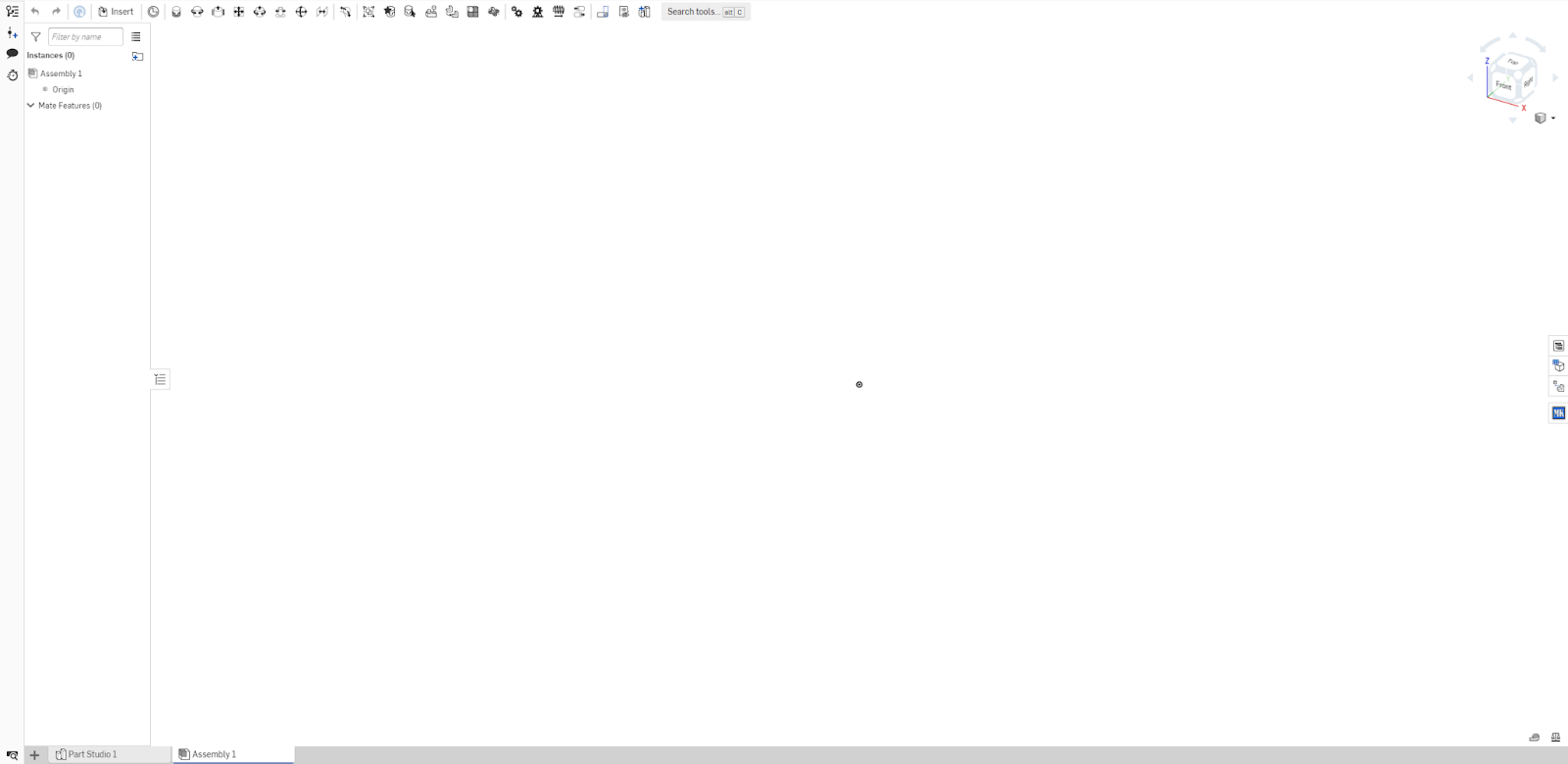
The Assembly can be found at the bottom of the screen by clicking on the tab labeled "Assembly 1." Click on the assembly and you will be shown to this empty screen:

In order to assemble individual parts into whole mechanisms, you must use the following steps:
- Insert the parts that you've made.
- Import other parts that you might need.
- Fix one of the parts to the 3D plane.
- Mate the parts together.
Steps 1 & 2:
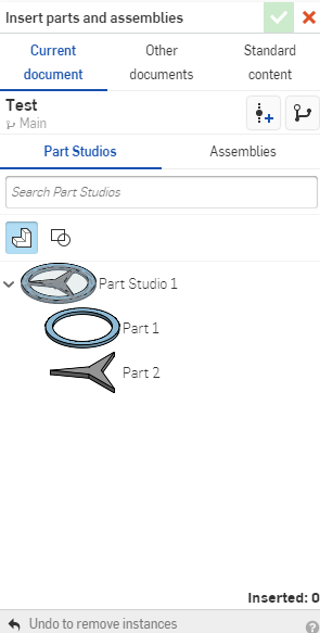
Click the insert button at the top left of the screen. This gives us an interface:

These parts are directly from the part studio that we made earlier. Click the green arrow after you are done to confirm. If you want to add items from other documents, or would like to add nuts and bolts, select the “Other Documents” tab, or “Standard Content” tab. Follow the same steps as above to insert the parts.
Step 3:
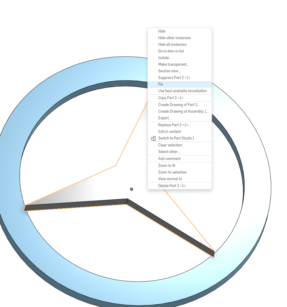
Right click one of the parts that you have just imported and find fix. This ensures that it can't move around freely, helping you assemble with more ease.

Step 4:
There are many different types of mates in Onshape that declare the relationship between two parts. Some allow for the entire assembly to rotate, translate, etc. This is useful for when you want a visual representation of your final mechanism.
Fastened Mate

Mates two entities and removes all degrees of freedom between them. This is the most basic type of mate. The popup is as follows:
Here, you can select the direction, angle, and offset.
Revolute Mate

Mate two entities allowing rotational movement about the Z axis. The interface is similar, but you can set limits of rotation.
Slider Mate

Slider mates join two entities allowing translational movement along the z-axis. The first mate connector serves as the sliding point and the second mate connector serves as the stationary point.
Planar Mate

Planar mate allows translational movement along the x- and the y-axis and rotational movement about the x-axis. For example, imagine a plate on a table. It is able to slide around and rotate.
Cylindrical Mate

Mates two entities allowing translational movement along the z-axis and rotational movement about the z-axis.
Pin Slot Mate

Mates two entities allowing rotational movement about the z-axis and translational movement along the x-axis.
Ball Mate

Mates two entities, allowing rotational movement only.
Parallel Mate

Mates two entities allowing individual translational movement along any axis and parallel rotation along any axis.
Tangent Mate

Attach any two entities tangent to the selected faces or edges.